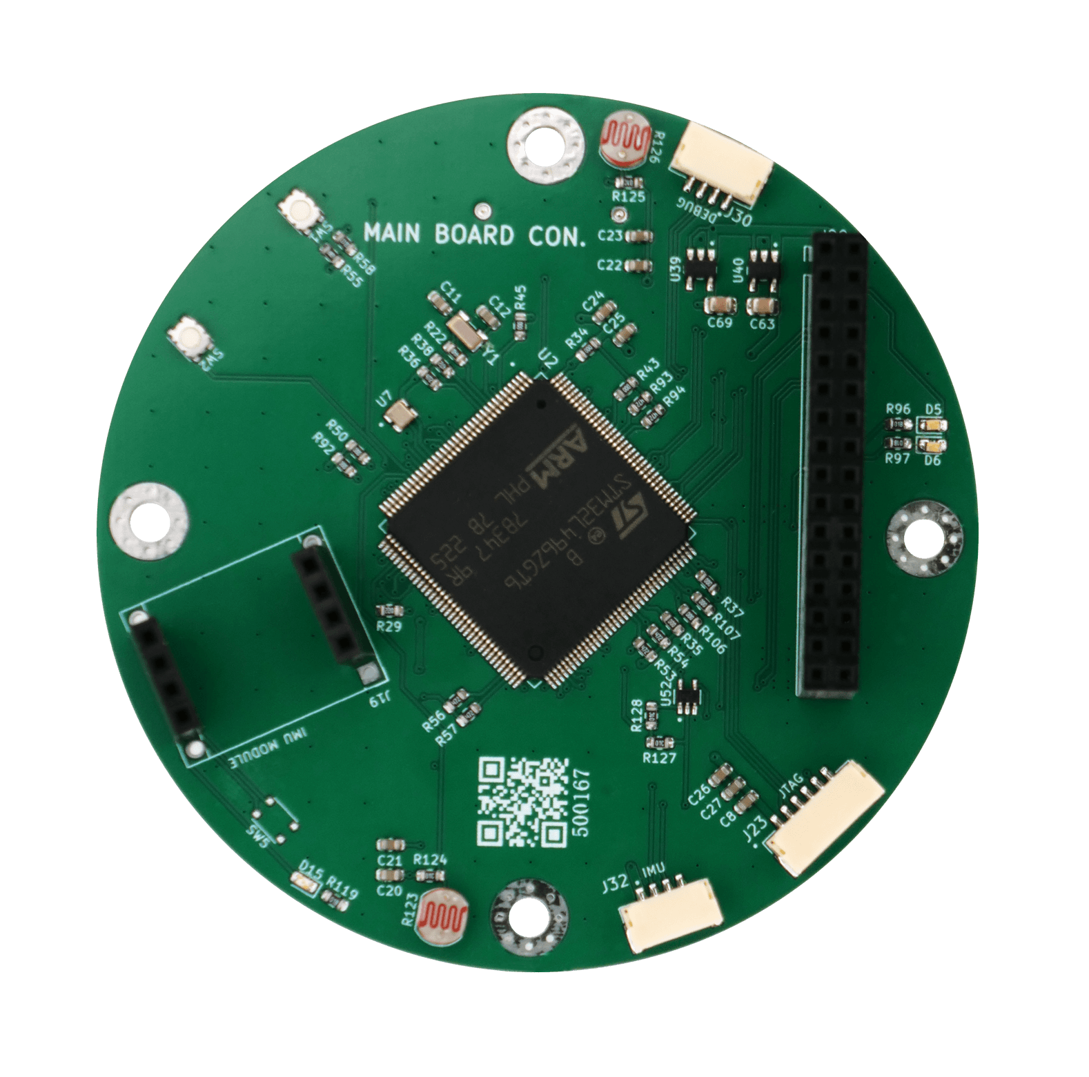
This is the main board of the Can Satellite (“Can Sat”).
At its core, it features an STM32-series microcontroller (MCU), and is structured with multiple ports arranged around it to interface with various sensors and communication modules.
Roles of the Main Board in a CanSat
Central Processing Unit (OBC, On-Board Computer)
The main board functions as the brain of the satellite, processing data collected from sensors, communication modules, and mission payloads such as cameras.
It is responsible for key functions including sensor data storage, command execution, communication control, and power distribution.
Sensor and Peripheral Control
The board interfaces with various components such as the IMU, GPS, barometric pressure sensor, and camera through protocols like I2C, UART, and SPI. It handles both data reception and command transmission.
Interface | Example Applications | Notes |
|---|---|---|
I2C | Barometric pressure sensor, IMU | Used for low-speed sensor communication |
UART | GPS module, communication module | Common for serial data transmission |
SPI | SD card, some camera modules | Suitable for high-speed data transfer |
GPIO | Parachute deployment, LED control | Used for general digital I/O operations |
Automated Mission Execution During Flight
The onboard software is programmed to autonomously execute key operations—such as camera activation, data transmission, and parachute deployment—upon reaching specific altitudes after launch.
Emergency handling routines, such as system reboot in case of communication failure, can also be implemented depending on the system state.
Data Storage and Transmission Control
Collected data is either stored on an SD card or transmitted to the ground station via a communication module.
The logged data can be retrieved and analyzed post-recovery for mission evaluation and research purposes.
CanSat Main Board – Example Mission Execution Workflow
Phase | Example Roles of the Main Board |
|---|---|
Immediately After Launch | System initialization → Sensor functionality check → Start mission timer |
During Ascent | Altitude measurement via GPS and barometric sensor / Rotation rate logging via IMU |
Upon Reaching Target Altitude | Trigger camera capture → Store data to SD card → Begin real-time transmission |
Descent Phase | Activate parachute deployment trigger → Analyze acceleration data → Switch to power-saving mode |
After Landing | Transmit final GPS-based location → Shut down or enter standby mode |
Board Configuration
Central MCU: STM32F4 series microcontroller
Bottom-left Sub-board: Voltage regulator or sensor module (e.g., IMU)
Peripheral Connectors: Interfaces for extension boards, sensors, and communication modules
The main board serves as the brain and control center of the CanSat. It acts as the central processing unit, responsible for integrating sensor data, executing mission tasks, and managing all onboard communications.